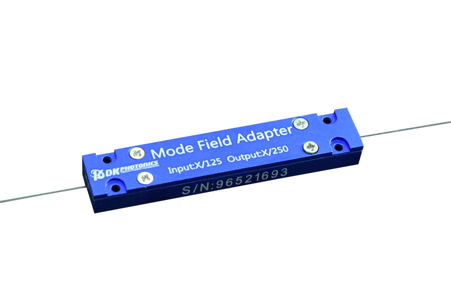
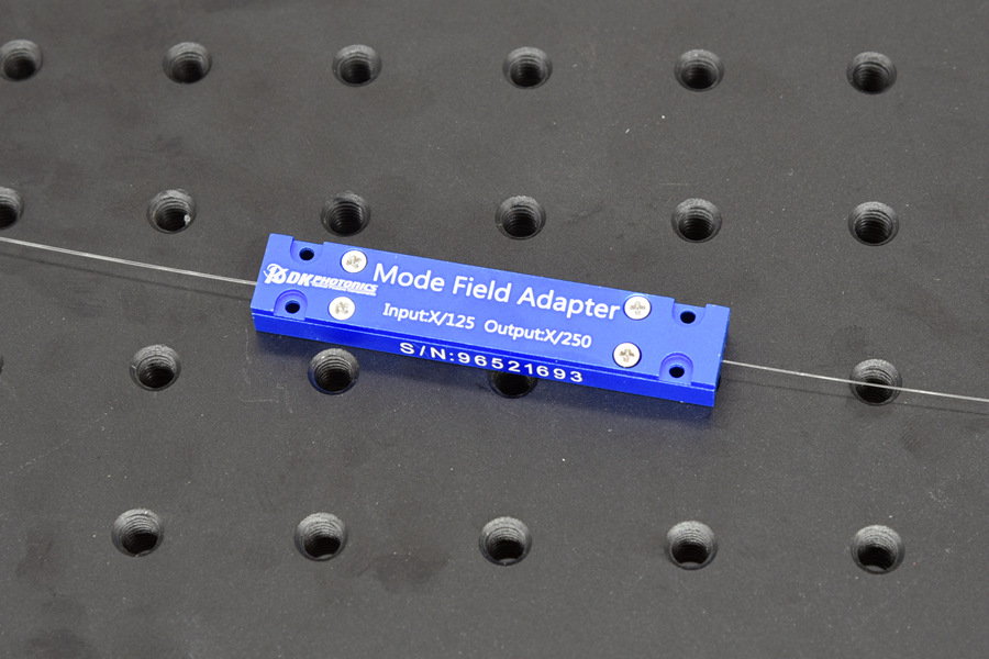
2.0μm Mode Field Adaptor
Mode field is different in fibers with different core diameter and NA. Splicing loss is large between two fibers with different mode field. In order to reduce splicing loss, mode field must be similar. MFA can optimize splice loss significantly, usually <0.5dB, even <0.3dB between different fibers.
2.0μm Mode Field Adaptors is designed to makes two fiber to keep mode field diameter matched with low fundamental mode signal loss and minimal degradation of beam quality (M2).These devices can also be used to absorb residual pump light in the reverse direction, preventing damage to the seed or isolator.
Define small MFD fiber to large MFD fiber is F-Forward, large MFD to small MFD is B-Backward. Custom Mode Field Adaptors can be designed to meet a wide range of fiber types.
| Features | Applications |
| · Low Insertion Loss
· High Power Handling · Custom Configurations Available |
· Fiber Lasers
· Fiber Amplifiers |
General Configuration for Forward MFA:
| Working Wavelength(nm) | Signal Input Fiber | Signal Output Fiber | Signal Insertion Loss (dB) | Max. Power Handling |
| 1950~2050 | SM1950 | 10/130µm,NA0.15/0.46 | ≤0.5 | 30W |
| 1950~2050 | 10/130µm,NA0.15/0.46 | 25/250µm,NA0.09/0.46 | ≤0.5 | 30W |
| 1950~2050 | PM1950 | PM10/130µm,NA0.15/0.46 | ≤0.5 | 30W |
| 1950~2050 | PM10/130µm,NA0.15/0.46 | PM25/250µm,NA0.09/0.46 | ≤0.5 | 100W |
General Configuration for Backward MFA:
| Working Wavelength(nm) | Signal Input Fiber | Signal Output Fiber | Signal Insertion Loss (dB) | Max. Power Handling |
| 1950~2050 | 10/130µm,NA0.15/0.46 | SM1950 | ≤0.5 | 20W |
| 1950~2050 | 25/250µm,NA0.09/0.46 | 10/130µm,NA0.15/0.46 | ≤0.7 | 50W |
| 1950~2050 | PM10/130µm,NA0.15/0.46 | PM1950 | ≤0.5 | 20W |
| 1950~2050 | PM25/250µm,NA0.09/0.46 | PM10/130µm,NA0.15/0.46 | ≤0.7 | 50W |
Remark:
- Other configuration and higher power handling can be customized.
- All MFA default with bare fiber, 0.8m length of pigtail, please contacts us for special request.
- The signal loss means the fundamental mode signal loss.
- ER≥18dB for PM fiber MFA.
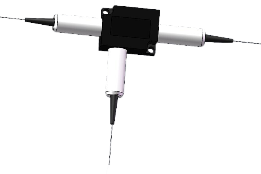
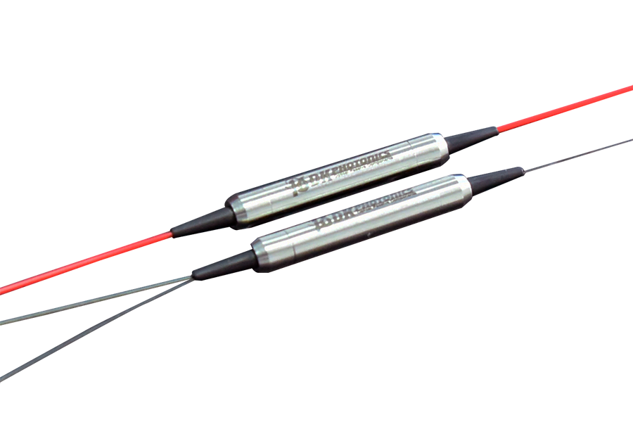
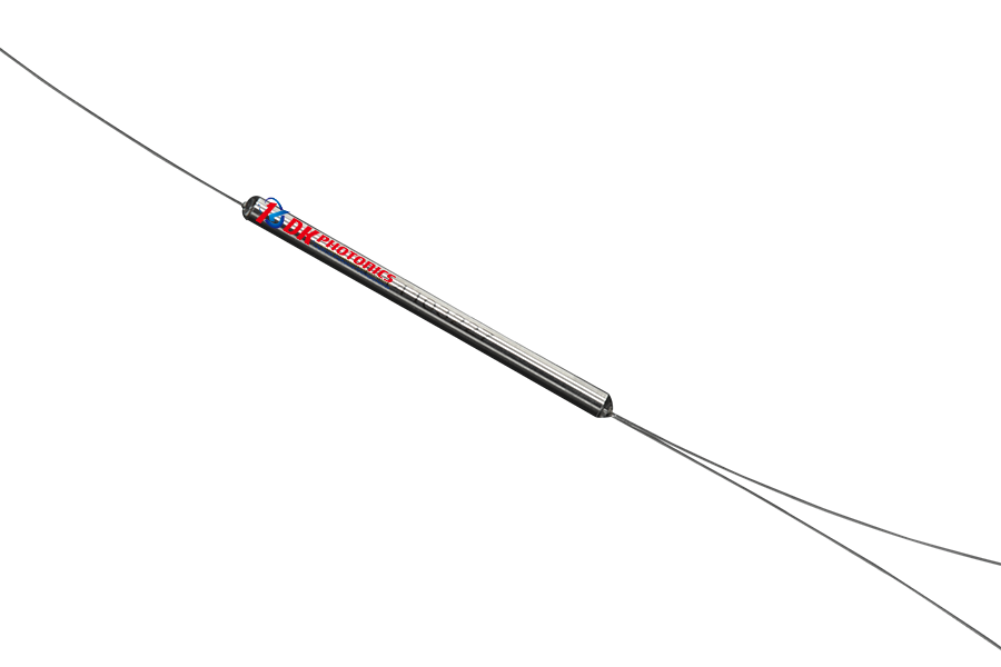
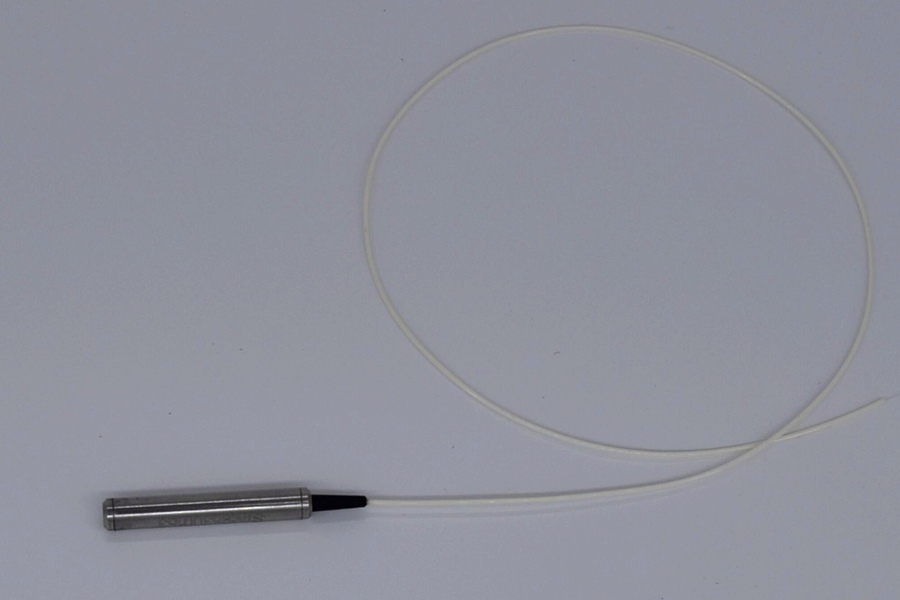
Package Information
| Package Type | P1 | P2 | P3 |
| Dimensions (mm) | Ф4.0×60 | 65x12x7 | 80x12x8 |
*Due to ongoing design improvements, the package size is subject to change. According to the different configuration, power handling, and fiber core diameter, we will choose the appropriate package size. Please contact DK Photonics for confirmation.
*Device package must be mounted onto heat sink (active cooling is suggested) with thermal paste for high power.
Order information P/N: MFA (PMMFA)-A-B-C-D-E-F
When you inquire, please provide the correct P/N number according to our ordering information, and attach the appropriate description would be better.
| A | B | C | D | E | F |
| Working Wavelength | Direction | Power Handling | Input Fiber Type | Output Fiber Type | Fiber length |
| 03:1030nm
64:1064nm 55:1550nm 20:2000nm |
F:Forward
B:Backward |
05:5W
10:10W 25:25W 50:50W XX: Other |
XXX(fiber name) | XXX(fiber name) | 08:0.8m(default)
10:1.0m 20:2.0m |
Part Number Example: MFA-2000-F-10-15/130/015/046-25/250/009/046 -10
Description: 2000nm Mode Field Adaptor, Forward, Max. 10W power handling, 15/130µm, 0.15/046NA input fiber, 25/250µm, 0.09/046NA output fiber, 1.0m fiber length,
Ordering Information for Custom Parts
If you need to customize other specifications, please provide detailed description for your requirement.
Request a quote
Please provide the following information so that we may process your quote quickly, Please let us know more about your inquiry. If you do not give us any information, we will think that you are not serious, and you might not get a reply from us.