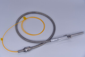
Optical passive components are key components in optical fiber networks and communication. They require no input power to function in an optical fiber system. Fiber optic connectors, fiber splicers, optical fiber jumpers, attenuators, divider, isolator, coupler, optical switch, wavelength division multiplexing, and so on are the most common and widely used passive optical components. These devices are used to split, combine, or alter signals in various manners for a variety of optical fiber applications.
Today, designers in various industries use these optical passive components to create more creative and cost-effective system designs to direct, control and filter optical signals for specific applications. They allow capacity upgrades in any system design at a relatively low cost without any additional construction works. So, if you are looking for a system upgrade using innovative optical passive components, this post will help you determine common test parameters and tools for passive component testing before system integration.

Common Test Parameters for Optical Passive Components
The scope and purpose of a particular device determine the parameters to be tested. The most common test parameters in passive component testing include:
Insertion Loss
It is the most basic test parameter for passive components. For insertions loss test, measure power through the same lead-in fiber to find out the input power to the DUT and output power from the DUT. Insertions loss is then calculated using formula 10log(Input Power/Output Power). It is a relative measurement and required for passive components including connectors, splitters, isolators, forward direction circulators, on-state switches, port attenuators, and many more.
Isolation
If your system design requires to block light signal, then you may consider conducting an isolation test. It is simply an insertion loss test where you are measuring a very low signal level. Passive components that require an isolation test include isolators, reverse direction circulators, reverse path modulators, off-state switches, and so on.
Split Ratio
The split ratio is a straightforward and relative measurement for splitters or tap devices. They are used to divide the light signal into two or more output signals without wavelength selection. A split ratio can be anything from 50/50 to 99/1.
Test Tools for Optical Passive Components
When you need to do these fundamental tests of passive components, it is important to get an optical power meter (OPM). It helps you measure the power in an optical signal to measure different test parameters. You may also need a visual fault locator (VFL) and optical light source (OLS) for different test functions to test optical loss and ratio. You can also get an optical time-domain reflectometer (OTDR) for the measurement of optical link loss in your system design. These are the basic tools for basic passive optical component testing.
Optical passive components are essential in today’s fiber-optic network and communication. An accurate and precise passive component testing is essential for the stability of the fiber network. These test parameters help you find the tight optical passive components for your custom fiber solutions. For more details, contact us at DK Photonics for professional support and help.

Leave A Comment